
Matrix Display
Description
A matrix display, also known as a dot matrix display or pixel display, is a type of electronic display that consists of a grid of individual pixels arranged in rows and columns. Each pixel in the display can be independently controlled, allowing for the creation of text, symbols, or images.
Sensor Details
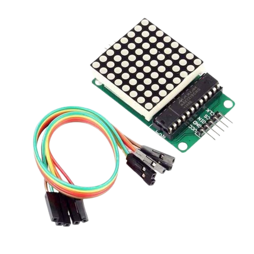
The MAX7219 IC is commonly used in conjunction with dot matrix displays, specifically LED dot matrix displays. The MAX7219 simplifies the process of controlling the individual LEDs within the dot matrix, allowing for the display of text, numbers, symbols, and even basic graphics.
Here's how the MAX7219 IC can be used with a dot matrix display:
-
Connection: The MAX7219 IC is connected to the dot matrix display using the appropriate wiring. The wiring typically involves connecting the pins of the MAX7219 (such as data, clock, and load) to the corresponding pins of the dot matrix display. The specific pinout and wiring details may vary depending on the dot matrix display being used.
-
Data and Control: The microcontroller or control circuit communicates with the MAX7219 IC to control the dot matrix display. This is achieved by sending commands and data over the serial interface of the MAX7219. The microcontroller provides the necessary data (such as characters, symbols, or graphics) to be displayed on the dot matrix.
-
Multiplexing and Scanning: The MAX7219 handles the multiplexing and scanning of the dot matrix display. It scans through the rows or columns of the dot matrix at a high speed, turning on or off the individual LEDs as needed. This multiplexing technique creates the illusion of a stable image or text on the display.
-
Control Functions: The MAX7219 provides control functions to control various aspects of the dot matrix display. This includes brightness control, enabling or disabling specific LEDs, and setting the decoding mode for input data (such as BCD or hexadecimal).
By utilizing the MAX7219 IC with a dot matrix display, you can create dynamic and customizable visual content. The microcontroller or control circuit sends the appropriate commands and data to the MAX7219, which then controls the dot matrix display accordingly. This allows for the display of scrolling text, animations, and other visual effects.
Overall, the combination of the MAX7219 IC and a dot matrix display offers a convenient and efficient solution for driving LED dot matrix displays, making it a popular choice in applications such as message boards, information displays, and small graphical interfaces.
Wiring Details
- Arduino 5V to MAX7219 Matrix Display Vcc+
- Arduino GND to MAX7219 Matrix Display GND
- Arduino PIN 10 to MAX7219 Matrix Display PIN LOAD
- Arduino PIN 11 to MAX7219 Matrix Display PIN CLK
- Arduino PIN 12 to MAX7219 Matrix Display PIN DATA
Circuit Image

Circuit Code
#include "LedControl.h" //  need the library


LedControl lc=LedControl(12,11,10,1); // lc is our object

// pin 12 is connected to the MAX7219 pin 1

// pin 11 is connected to the CLK pin 13

// pin 10 is connected to LOAD pin 12

// 1 as we are only using 1 MAX7219

void setup()

{

  // the zero refers to the MAX7219 number, it is zero for 1 chip

  lc.shutdown(0,false);  // turn off power saving, enables display

  lc.setIntensity(0,8);   // sets brightness (0~15 possible values)

  lc.clearDisplay(0);   // clear screen

}

void loop()

{

  for (int a=0; a<8; a++)

  {

    lc.setDigit(0,a,a,true);

    delay(100);

  }

  for (int a=0; a<8; a++)

  {

    lc.setDigit(0,a,8,1);

    delay(100);

  }

  for (int a=0; a<8; a++)

  {

    lc.setDigit(0,a,0,false);

    delay(100);

  }

  for (int a=0; a<8; a++)

  {

    lc.setChar(0,a,' ',false);

    delay(100);

  }

  for (int a=0; a<8; a++)

  {

    lc.setChar(0,a,'-',false);

    delay(100);

  }

  for (int a=0; a<8; a++)

  {

    lc.setChar(0,a,' ',false);

    delay(100);

  }

}