
LCD display
Description
The LiquidCrystal library allows you to control LCD displays that are compatible with the Hitachi HD44780 driver. There are many of them out there, and you can usually tell them by the 16-pin interface.
Sensor Details
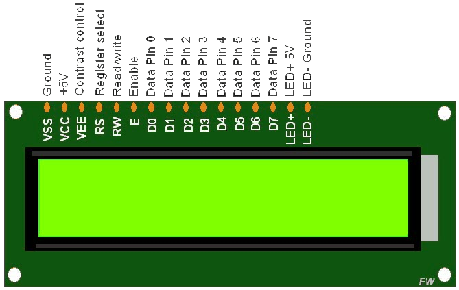
The LCDs have a parallel interface, meaning that the microcontroller has to manipulate several interface pins at once to control the display. The interface consists of the following pins:
- A register select (RS) pin that controls where in the LCD's memory you're writing data to. You can select either the data register, which holds what goes on the screen, or an instruction register, which is where the LCD's controller looks for instructions on what to do next.
- A Read/Write (R/W) pin that selects reading mode or writing mode
- An Enable pin that enables writing to the registers
- 8 data pins (D0 -D7). The states of these pins (high or low) are the bits that you're writing to a register when you write, or the values you're reading when you read.
There's also a display contrast pin (Vo), power supply pins (+5V and GND) and LED Backlight (Bklt+ and BKlt-) pins that you can use to power the LCD, control the display contrast, and turn on and off the LED backlight, respectively.
The process of controlling the display involves putting the data that form the image of what you want to display into the data registers, then putting instructions in the instruction register. The LiquidCrystal Library simplifies this for you so you don't need to know the low-level instructions.
The Hitachi-compatible LCDs can be controlled in two modes: 4-bit or 8-bit. The 4-bit mode requires seven I/O pins from the Arduino, while the 8-bit mode requires 11 pins. For displaying text on the screen, you can do most everything in 4-bit mode, so example shows how to control a 16x2 LCD in 4-bit mode.
Wiring Details
- Connect LCD Vcc/Vdd pin to Vcc pin of Arduino
- Connect LCD GND pin to GND pin of Arduino
- Connect LCD RS pin to digital pin 12 of Arduino
- Connect LCD Enable pin to digital pin 11 of Arduino
- Connect LCD R/W pin to GND pin of Arduino because we are going to do ‘write’ action only.
- Connect LCD D4 pin to digital pin 5 of Arduino
- Connect LCD D5 pin to digital pin 4 of Arduino
- Connect LCD D6 pin to digital pin 3 of Arduino
- Connect LCD D7 pin to digital pin 2 of Arduino
- Connect LCD Contrast pin Vo to wiper (pin 2) of 10K POT and connect pin 1 of POT to Vcc and pin 3 to GND
- Connect LCD Backlight(+) pin to Vcc along with current limiting resistor of 220 Ohm
- Connect LCD Backlight(-) pin to GND
Circuit Image

Circuit Code
                                            /*

  The circuit:

 * LCD RS pin to digital pin 12

 * LCD Enable pin to digital pin 11

 * LCD D4 pin to digital pin 5

 * LCD D5 pin to digital pin 4

 * LCD D6 pin to digital pin 3

 * LCD D7 pin to digital pin 2

 * LCD R/W pin to ground

 * LCD VSS pin to ground

 * LCD VCC pin to 5V

 * 10K resistor:

 * ends to +5V and ground

 * wiper to LCD VO pin (pin 3)


*/

// include the library code:

#include <LiquidCrystal.h>

// initialize the library by associating any needed LCD interface pin

// with the arduino pin number it is connected to

const int rs = 12, en = 11, d4 = 5, d5 = 4, d6 = 3, d7 = 2;

LiquidCrystal lcd(rs, en, d4, d5, d6, d7);

void setup() {

  // set up the LCD's number of columns and rows:

  lcd.begin(16, 2);

  // Print a message to the LCD.

  lcd.print("hello, world!");

}

void loop() {

  // set the cursor to column 0, line 1

  // (note: line 1 is the second row, since counting begins with 0):

  lcd.setCursor(0, 1);

  // print the number of seconds since reset:

  lcd.print(millis() / 1000);

}