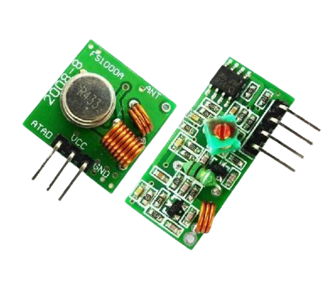


RF Module
Description
An RF (Radio Frequency) module is a compact electronic device that allows wireless communication between devices using radio waves. It typically consists of a transmitter and a receiver, allowing data to be transmitted and received wirelessly over a certain frequency band.
RF modules are commonly used in various applications, including remote controls, wireless data transmission, Internet of Things (IoT) devices, wireless sensor networks, wireless communication between microcontrollers or embedded systems, and more.
Sensor Details
-
Transmitter: The transmitter part of the module is responsible for encoding the data from the source device (such as a sensor or a microcontroller) into radio waves and transmitting them through an antenna.
-
Receiver: The receiver part of the module receives the radio signals from another RF module or transmitter and decodes the data for use by the receiving device.
-
Antenna: The antenna is a crucial part of the RF module, as it helps transmit or receive radio signals effectively.
-
Frequency: RF modules operate on specific frequency bands, such as 433MHz, 868MHz, 2.4GHz, etc. The choice of frequency depends on the application requirements and regulations in the region where the devices will be used.
-
Modulation: The data transmitted over the RF module is modulated onto the radio carrier wave using various modulation techniques like Amplitude Shift Keying (ASK), Frequency Shift Keying (FSK), or Phase Shift Keying (PSK).
-
Protocol: RF modules often follow specific communication protocols, which define how data is structured, transmitted, and received. Some common protocols include UART, SPI, I2C, etc.
-
Range: The communication range of RF modules varies depending on the power output, frequency, and environmental factors. Generally, they can achieve ranges from a few meters to several kilometers in open spaces.
Receiver Module specification :
Operation voltage: DC5V
Static Current: 4MA
Receiver frequency: 433.92MHZ; 315 Mhz
Sensitivity:-105DB
Dimension:30*14*9mm
External Antenna:32CM signal wire, spiral
Transmitter Module Specification :
Operating voltage: 3-12V
Operating frequency: 433.92MHz; 315Mhz
Standby current: 0mA
Operating current :20-28mA
Transmission distance:> 500m (open to receiving plate sensitivity at-103dBm distance of more than)
Output Power: 16dBm (40mW)
Transfer rate: <10Kbps
Modulation mode: OOK (Amplitude Modulation)
Operating Temperature: -10 ℃ ~ +70 ℃
Size: 19 × 19 × 8mm
|
General Specification |
|
|
Transmitter specification |
As per below |
|
Operating voltage |
3-12V |
|
Operating frequency |
433.92MHz; 315Mhz |
|
Operating current |
20 – 28 mA |
|
Transmission distance |
> 500 m |
|
Output Power |
16dBm (40mW) |
|
Transfer rate |
<10Kbps |
|
Dimensions (mm) |
19 x 19 x 8 (L x W x H) |
|
Receiver specification |
As per below |
|
Operation voltage |
DC 5V |
|
Receiver frequency |
433.92MHZ; 315 Mhz |
|
Sensitivity |
-105DB |
|
External Antenna |
32CM signal wire,spiral |
|
Dimensions(mm) |
30 x 14 x 9 (L x W x H) |
|
Shipment Weight |
0.06 kg |
|
Shipment Dimensions |
5 × 5 × 3 cm |
Wiring Details
For the RF transmitter module:
Connect the VCC pin of the RF transmitter module to the 5V pin on the Arduino.
Connect the GND (ground) pin of the RF transmitter module to the GND pin on the Arduino.
Connect the data pin of the RF transmitter module to a digital pin on the Arduino. The specific pin can be chosen according to your preference, but ensure it is compatible with the chosen Arduino board (check the pin capabilities and availability).
For the RF receiver module:
Connect the VCC pin of the RF receiver module to the 5V pin on the Arduino.
Connect the GND (ground) pin of the RF receiver module to the GND pin on the Arduino.
Connect the data pin of the RF receiver module to a digital pin on the Arduino. Similar to the transmitter, choose a pin compatible with your Arduino board.
Circuit Image

Circuit Code
                                            TX Code


//simple Tx on pin D12


#include


int s=8;


char *controller;


void setup() {


  Serial.begin(9600);


  pinMode(13,OUTPUT);


  pinMode(s,INPUT);


vw_set_ptt_inverted(true); //


vw_set_tx_pin(12);


vw_setup(4000);// speed of data transfer Kbps


}


void loop(){


  int x=digitalRead(s);


Serial.println(x);


delay(500);


  if(x==1){


controller="A1"  ;


vw_send((uint8_t *)controller, strlen(controller));


vw_wait_tx(); // Wait until the whole message is gone


digitalWrite(13,1);


delay(1000);


digitalWrite(13,0);


delay(1000);


controller="B1"  ;


vw_send((uint8_t *)controller, strlen(controller));


vw_wait_tx(); // Wait until the whole message is gone


digitalWrite(13,1);


delay(1000);


digitalWrite(13,0);


delay(1000);


}


}


 /////////////////////////////////////////////////////////////////////////////


RXCode


//simple Tx on pin D12


#include


void setup()


{


    vw_set_ptt_inverted(true); // Required for DR3100


    vw_set_rx_pin(12);


    vw_setup(4000);  // Bits per sec


    pinMode(13, OUTPUT);


    vw_rx_start();       // Start the receiver PLL running


}


    void loop()


{


    uint8_t buf[VW_MAX_MESSAGE_LEN];


    uint8_t buflen = VW_MAX_MESSAGE_LEN;


    if (vw_get_message(buf, &buflen)) // Non-blocking


    {


      if((buf[0]=='A')&&(buf[1]=='1')){


      digitalWrite(13,1);


      delay(1000);


      }


      }


      else{


  digitalWrite(13,0);


    }


}