

Gyro-Accelerometer
Description
The sensor module for MPU6050 is a small device that tracks motion in 6 axes. It includes a 3-axis gyroscope, a 3-axis accelerometer, and a digital motion processor. Additionally, it has a built-in temperature sensor for extra features. The module can communicate with microcontrollers through its I2C bus interface.
Additionally, the module has an Auxiliary I2C bus that enables communication with other sensor devices such as a 3-axis Magnetometer or a Pressure sensor. If a 3-axis Magnetometer is connected to the auxiliary I2C bus, the MPU6050 sensor module can provide a complete 9-axis Motion Fusion output.
Sensor Details
The "gyroscope sensor 6050" likely refers to the MPU-6050, which is a popular gyroscope and accelerometer sensor module. The MPU-6050 is a MEMS (Microelectromechanical Systems) device that combines a 3-axis gyroscope and a 3-axis accelerometer in a single chip.
Key features of the MPU-6050 include:
3-Axis Gyroscope: The gyroscope measures angular velocity along three axes (X, Y, and Z) and provides information about the device's orientation and rotation.
3-Axis Accelerometer: The accelerometer measures linear acceleration along three axes (X, Y, and Z) and can be used to determine the device's movement and orientation with respect to gravity.
3-Axis Gyroscope
The MPU6050 consist of 3-axis Gyroscope with Micro Electro Mechanical System(MEMS) technology. It is used to detect rotational velocity along the X, Y, Z axes as shown in below figure.

- When the gyros are rotated about any of the sense axes, the Coriolis Effect causes a vibration that is detected by a MEM inside MPU6050.
- The resulting signal is amplified, demodulated, and filtered to produce a voltage that is proportional to the angular rate.
- This voltage is digitized using 16-bit ADC to sample each axis.
- The full-scale range of output are +/- 250, +/- 500, +/- 1000, +/- 2000.
- It measures the angular velocity along each axis in degree per second unit.
3-Axis Accelerometer
The MPU6050 consist 3-axis Accelerometer with Micro Electro Mechanical (MEMs) technology. It used to detect angle of tilt or inclination along the X, Y and Z axes as shown in below figure.

- Acceleration along the axes deflects the movable mass.
- This displacement of moving plate (mass) unbalances the differential capacitor which results in sensor output. Output amplitude is proportional to acceleration.
- 16-bit ADC is used to get digitized output.
- The full-scale range of acceleration are +/- 2g, +/- 4g, +/- 8g, +/- 16g.
- It measured in g (gravity force) unit.
- When device placed on flat surface it will measure 0g on X and Y axis and +1g on Z axis.
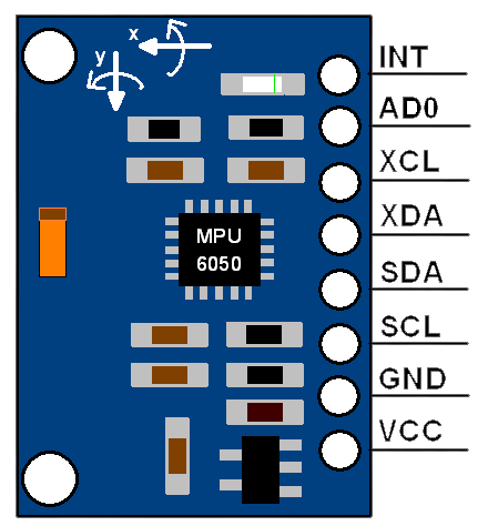
MPU6050 Pin Description
The MPU-6050 module has 8 pins,
- INT: Interrupt digital output pin.
- AD0: I2C Slave Address LSB pin. This is 0th bit in 7-bit slave address of device. If connected to VCC then it is read as logic one and slave address changes.
- XCL: Auxiliary Serial Clock pin. This pin is used to connect other I2C interface enabled sensors SCL pin to MPU-6050.
- XDA: Auxiliary Serial Data pin. This pin is used to connect other I2C interface enabled sensors SDA pin to MPU-6050.
- SCL: Serial Clock pin. Connect this pin to microcontrollers SCL pin.
- SDA: Serial Data pin. Connect this pin to microcontrollers SDA pin.
- GND: Ground pin. Connect this pin to ground connection.
- VCC: Power supply pin. Connect this pin to +5V DC supply.
- MPU-6050 module has Slave address (When AD0 = 0, i.e. it is not connected to Vcc) as,
- Slave Write address(SLA+W): 0xD0
- Slave Read address(SLA+R): 0xD1
Specification of MPU6050 Sensor
Gyroscope:
- 3-axis sensing with a full-scale range of ±250, ±500, ±1000, or ±2000 degrees per second (dps)
- Sensitivity of 131, 65.5, 32.8, or 16.4 LSBs per dps
- Output data rate (ODR) range of 8kHz to 1.25Hz
Accelerometer:
- 3-axis sensing with a full-scale range of ±2g, ±4g, ±8g, or ±16g
- Sensitivity of 16384, 8192, 4096, or 2048 LSBs per g
- ODR range of 8kHz to 1.25Hz
- Temperature Sensor:
- Operating range of -40°C to +85°C
- Sensitivity of 340 LSBs per degree Celsius
- Accuracy of ±3°C
Supply Voltage:
- Operating voltage range of 2.375V to 3.46V for the MPU-6050, and 2.375V to 5.5V for the MPU-6050A
- Communication Interface:
- I2C serial interface with a maximum clock frequency of 400kHz
- 8-bit and 16-bit register access modes
Other Features:
- Digital Motion Processor (DMP) for complex motion processing
- On-chip 16-bit ADCs for accurate analog-to-digital conversion
- Programmable digital filters for improved noise performance
- Interrupts for triggering events based on specific motion conditions
- Low-power consumption (3.9mA for full operation)
Wiring Details
Connections:
- Connect VCC and GND pins of MPU-6050 to 5V and GND of Arduino, respectively.
- Connect SDA and SCL pins of MPU-6050 to the corresponding SDA and SCL pins on the Arduino board. On most Arduino boards, SDA is labeled as A4, and SCL is labeled as A5.
Once the connections are made, follow these steps:
Install the necessary libraries:
Open the Arduino IDE on your computer.
Go to "Sketch" > "Include Library" > "Manage Libraries."
Search for "MPU6050" and install the "MPU6050" library by Jeff Rowberg.
Also, install the "Wire" library if you haven't already (it should be pre-installed with the Arduino IDE).
Circuit Image

Circuit Code
                                            #include <Wire.h>

const int MPU = 0x68;  // MPU-6050 I2C address

int16_t AcX, AcY, AcZ, GyX, GyY, GyZ;

void setup() {

  Wire.begin();

  Wire.beginTransmission(MPU);

  Wire.write(0x6B);  // Power management register

  Wire.write(0);     // Wake up the MPU-6050

  Wire.endTransmission(true);

  Serial.begin(9600);

}

void loop() {

  Wire.beginTransmission(MPU);

  Wire.write(0x3B);  // Starting register for accelerometer data

  Wire.endTransmission(false);


  Wire.requestFrom(MPU, 14, true); // Request 14 bytes of data

  AcX = Wire.read() << 8 | Wire.read();

  AcY = Wire.read() << 8 | Wire.read();

  AcZ = Wire.read() << 8 | Wire.read();

  int16_t Temp = Wire.read() << 8 | Wire.read(); // Temperature

  GyX = Wire.read() << 8 | Wire.read();

  GyY = Wire.read() << 8 | Wire.read();

  GyZ = Wire.read() << 8 | Wire.read();

  // Print the sensor data

  Serial.print("Accelerometer: ");

  Serial.print("X = "); Serial.print(AcX);

  Serial.print(" | Y = "); Serial.print(AcY);

  Serial.print(" | Z = "); Serial.println(AcZ);

  Serial.print("Gyroscope: ");

  Serial.print("X = "); Serial.print(GyX);

  Serial.print(" | Y = "); Serial.print(GyY);

  Serial.print(" | Z = "); Serial.println(GyZ);


  // Print temperature in degrees Celsius

  float temperature = (Temp / 340.0) + 36.53;

  Serial.print("Temperature: ");

  Serial.println(temperature);

  delay(1000); // Delay for readability

}