

Buzzer
Description
This article will cover buzzer interfacing with Arduino.Active piezo buzzer example code, we’ll simply sound the buzzer for 3 seconds followed by two seconds of silence and then repeat. And passive piezo buzzer example code, we will create the standard alarm signal example that cycles the sound of the passive buzzer.
Sensor Details
Active and passive buzzers are two types of electronic components used to produce sound in various applications. Here's a brief explanation of each:
Active Buzzer: An active buzzer is a type of electronic audio signaling device that generates sound when it receives an electrical signal. It consists of a built-in oscillator circuit and a sound-generating mechanism. When a voltage is applied to the active buzzer, it produces a continuous or intermittent sound without the need for an external audio signal. Active buzzers are typically driven by a square wave signal at a specific frequency to produce different tones or melodies. They are commonly used in alarms, timers, electronic games, and other devices that require audible alerts.
Passive Buzzer: A passive buzzer, on the other hand, is a sound-producing component that requires an external audio signal to produce sound. It does not have an internal oscillator or sound-generating mechanism like an active buzzer. Instead, it acts as a simple transducer that converts an electrical signal into an audible sound. A passive buzzer needs an alternating current (AC) signal of the appropriate frequency to generate sound. When the AC signal is applied, the buzzer vibrates and produces sound. The frequency of the input signal determines the pitch of the sound produced by the passive buzzer. Passive buzzers are commonly used in electronic projects, musical instruments, and devices that require different tones or melodies.
In summary, an active buzzer can generate sound on its own when powered, while a passive buzzer requires an external audio signal to produce sound.
Wiring Details
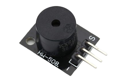
Module GND to Arduino GND
Module Signal to Arduino PIN 13
Module Vcc+ to No Connection
Circuit Image


Circuit Code
//  for Active Buzzer

int GPActiveBuzzer = 13;


void setup ()

{

  pinMode (GPActiveBuzzer, OUTPUT); // set pin to output mode

}


void loop () //Main program loop

{

  digitalWrite (GPActiveBuzzer, HIGH); // sound the buzzer

  delay (3000); // pause code for 3 seconds

  digitalWrite (GPActiveBuzzer, LOW); // stop the buzzer

  delay (2000); // pause code for 2 seconds

}


--------------------------------------------------------------------------------------------

//for Passive buzzer

int buzzer = 12 ;


void setup ()

{

  // set our pin to output mode

  pinMode (buzzer, OUTPUT) ;

}


void loop ()

{

  // loop through frequencies to generate alarm sound

  unsigned char i;

  while (1)

  {

    //Frequency 1

    for (i = 0; i <80; i++)

    {

      digitalWrite (buzzer, HIGH) ;

      delay (1) ;

      digitalWrite (buzzer, LOW) ;

      delay (1) ;

    }

    //Frequency 2

    for (i = 0; i <100; i++)

    {

      digitalWrite (buzzer, HIGH) ;

      delay (2) ;

      digitalWrite (buzzer, LOW) ;

      delay (2) ;

    }

  }

}